
Air / Fuel Management
Air and Fuel Management
The air / fuel management system on OBD II equipped vehicles is responsible for accurately measuring all the air entering the engine then delivering the precise amount of fuel to each cylinder that will achieve good performance, optimal fuel efficiency and low tail pipe emissions. Air flow through the engine is either measured by a sensor inserted in the air intake duct or calculated by the PCM through precise measurement of intake manifold pressure, throttle position and engine speed.
All the air entering the engine needs to be accounted for by this system in order for the PCM to calculate the correct amount of fuel to be added to the air/fuel mixture; resulting in complete combustion and proper catalytic converter operation. If unmeasured air enters the engine not enough fuel will be added resulting in incomplete combustion and misfires. Under these conditions the engine is less fuel efficient and runs the risk of adding excessive pollution back into the air we breathe.
From a fuel delivery perspective, all OBD II vehicles use fuel injection to measure, atomize and distribute fuel to the engine’s cylinders. Most OBD II systems are configured with multi-point injection systems. With multi-point injection systems there is a separate fuel injector for each cylinder; fuel is sprayed directly into the cylinder head intake port or directly into the cylinder. This allows the air/fuel mixture to be about the same in all of the cylinders for better fuel efficiency, lower emissions and greater performance.
How rich or lean the air/fuel mixture being combusted by the engine is determined by varying the duration of the injector pulses (called pulse width). The longer the pulse width, the greater the volume of fuel delivered and the richer the mixture. Fuel Injector timing and injector pulse width are controlled by the PCM. The computer uses input from its various engine sensors to regulate fuel metering and to change the air/fuel ratio in response to changing operating conditions. The primary sensor for real-time adjustment to air/fuel mixture is the upstream oxygen sensor. The sensor generates a RICH or LEAN signal that the PCM uses to constantly adjust the fuel mixture.
In order for the PCM to control fuel injection correctly, the fuel delivery system needs to supply properly pressurized fuel to each injector and the correct amount of fuel must flow through the injectors with each injector pulse. Fuel pressure problems, inoperable injectors and even slightly clogged injectors will result in improper air/fuel mixture reaching the cylinders. Under these conditions incomplete combustion and misfires can occur.
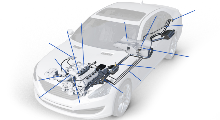
Let’s take a look at the function of some key components of the Air / Fuel Management System in greater detail.
Fuel Tank
The fuel tank stores fuel until it is needed by the injectors for combustion in the engine. It is usually constructed from metal or composite plastic materials. The fuel tank has an inlet pipe and an outlet pipe. The outlet pipe has a fitting for fuel line connection and may be located in the top or in the side of the tank. The lower end is about one-half inch above the bottom of the tank and will be fitted with a sock type of filter strainer so that collected sediment will not be brought into the rest of the fuel delivery system or injectors. Many OBD II vehicles will have the fuel pump and fuel filter housed in the fuel tank. On most tanks the bottom of the tank contains a drain plug so that tank may be drained and cleaned.
The tank is usually located at the opposite end of the vehicle from the engine and some vehicles may have multiple tanks for higher fuel capacity. Ruptures or failures to the lower portions of the fuel tank result in obvious fuel leaks. Failures located on top of the tank may not result in visible fuel leakage but will allow evaporative emissions (gasoline fumes) to escape into the atmosphere. On OBD II equipped vehicles these failures will be identified during EVAP monitoring.
Gas Cap
Gas caps are among the most critical components of the fuel system and if not correctly designed, calibrated and installed can cause the OBD II system to display a warning message to the motorist. Gas caps can be vented or non-vented and need to be replaced with the appropriate style cap for the EVAP system to operate without causing performance or Check Engine light issues.
Most gas caps on OBD II equipped vehicles allow fresh air into the fuel tank equalizing internal and atmospheric pressure, compensating for the fuel volume lost during normal emptying of the tank through driving. The gas caps also allow virtually no gasoline vapors or liquid fuel to push back into the atmosphere from built up vapor pressure from gasoline evaporation in the fuel tank or during a vehicle rollover. This is accomplished through air-tight sealing of the cap to the filler neck and versatile internal sealing diaphragms and sensitive springs.
On OBD II vehicles, gas cap failures are pretty common. Gas cap failures are discovered when the PCM runs the EVAP monitor during normal engine operation. When the EVAP monitor fails to run correctly the PCM stores a DTC fault code and illuminates the Check Engine light. For failed or loose gas caps the PCM usually set a P0440 DTC code indicating a large leak is present.
Fuel Tank Filler Neck
The fuel tank filler neck is usually a vented metal or rigid plastic pipe attached to the fuel tank through an air-tight flexible junction on one end; with the inlet end configured with fuel restriction hardware and access for re-fueling vapor venting. The top of the filler neck may be flanged and threaded keyed to accept and seal a gas cap. Newer filler necks may be capless in design with a spring loaded self sealing flapper in place of a traditional gas cap.
Fuel Pump
Fuel injection systems operate at high fuel pressures, typically in the 40-60 psi range, or higher for direct injection. To achieve proper pressure and volume flow fuel pumps are generally electric motors located in the fuel tank, utilizing the fuel in the tank to cool the pump and to ensure a steady supply of fuel.
On OBD II equipped vehicles the PCM controls the power to the fuel pump. The PCM on most systems operates the pump through the fuel pump relay during normal engine operation and can shut the pump off if the vehicle is in a collision or if low oil pressure is indicated. With some OBD II vehicles the PCM controls fuel pressure through pulse-width modulation of the voltage to the pump; this allows a smaller and lighter electric motor to be used reducing electrical load.
In many fuel systems the pump is an integral part of the fuel tank sending unit assembly. The fuel sending unit assembly may be a combination of the electric fuel pump, the filter, the strainer, and electronic sensors used to measure the amount of fuel in the tank and tank pressure. Data from these sensors is used by the PCM and the dash fuel level gauge.
Low fuel system pressure due to the fuel pump can be caused by a defective pump or poor electrical connects to the pump or fuel pump relay. Partially clogged fuel filters or strainers or defective fuel pressure regulators can also cause low fuel pressure. High fuel pressure can be caused by restricted fuel return lines back to the tank or a defective fuel pressure regulator.
Fuel Lines
Fuel lines connect all components of the fuel system. The rigid lines are usually made of steel tubing that has been zinc plated, on some systems rigid plastic tubing is being used. Fuel lines are secured to the frame and engine, minimizing vibration and keeping them away from exhaust manifolds, exhaust pipes and mufflers. In attachment points where there is a lot of movement, for instance, between the firewall and engine short lengths of flexible fuel lines are used. These flexible lines are made from high pressure gasoline resistant rubber, braided steel or high pressure plastic fuel line. It is extremely important to replace fuel lines with suitable replacement components/materials and connection hardware. Leaking or damaged fuel lines can cause problems achieving proper fuel system pressure and safe system operation.
Fuel Rail
Fuel rails are used on engines with multi-point fuel injection systems. A fuel rail is basically a pipe or two connected pipes (sometimes called a fuel manifold) used to deliver fuel to the individual fuel injectors on the engine. The rail is designed to have a pocket or seat for each injector as well as an inlet for a fuel supply. Some fuel rails will have a return outlet for fuel flow back to the fuel tank. Fuel rails may incorporate an attached fuel pressure regulator and/or a fuel pressure sensor.
The function of the fuel rail is to distribute fuel to the inlet sided of the injector and to provide a leak-proof seal between the rail and the injector. Many fuel rails also help secure the outlet side of the fuel injector to the intake manifold. Fuel rail failures are very uncommon with the exception of seals. Fuel rail-to-injector seals are usually rubber composite “O” rings that can deteriorate over time and leak fuel.
Fuel Injectors
A fuel injector is an electronically controlled solenoid valve that opens and closes many times per second. When the injector is energized, an electromagnet moves a plunger that opens the valve allowing the pressurized fuel to squirt out through a tiny nozzle. The nozzle is designed to atomize the fuel for better combustion.
The PCM controls the amount of fuel delivered by cycling the injector voltage on and off very rapidly. The longer the pulse width, the greater the volume of fuel delivered and the richer the fuel mixture. Decreasing the duration of the injector signal pulse reduces the volume of fuel delivered and leans out the mixture.
Fuel injector related problems include leaking “O” rings on the nozzle side of the injector where they are inserted into the intake manifold and dirty fuel injectors. Leaky “O” rings allow unmeasured air to enter the cylinders and with dirty injectors, a buildup of fuel deposits restricts fuel flow and interferes with the creation of a good spray pattern. Both conditions can cause a lean fuel condition and misfiring resulting in poor performance and possible excessive exhaust emissions.
Fuel Pressure Regulator
The function of the fuel pressure regulator is to maintain the desired fuel pressure delivered to the fuel injector under all engine operating conditions. On most OBD II systems that use a fuel pressure regulator, the regulator maintains a constant pressure in the fuel rail. Compensation for manifold pressure variations is accomplished by the PCM through modification of base injector pulse width. The fuel pressure regulator may be mounted integral to the fuel rail, attached at the outlet of the fuel rail or located downstream of the fuel rail sometimes in the fuel tank.
On other injection systems the fuel pressure regulator maintains a constant pressure between intake manifold pressure and the fuel rail. In this configuration, the regulator has a spring controlled vacuum diaphragm connected to the intake manifold pressure. The regulator decreases fuel pressure under light load and increases it under heavy load conditions. The excess fuel pressure passes through a bypass port back to the fuel tank to maintain the desired pressure differential. Most systems are calibrated to maintain a pressure differential of somewhere between 40 and 80 psi.
Fuel pressure regulator failures include leaking regulators that leak fuel externally or fuel pressure regulators that fail to maintain desired fuel pressure. Fuel pressure regulators that cannot maintain correct fuel system pressure will result in a fuel system creating either too lean or too rich of an air/fuel mixture for good performance and effective tail pipe emissions control.
Mass Air Flow Sensor
The mass air flow sensor (MAF) is used to measure the flow rate of air entering a fuel injected engine. The PCM uses air mass information to calculate and deliver the correct amount of fuel to the cylinders under all engine operating conditions. The sensor is located in the air induction piping before the throttle body and produces an electrical signal to the PCM that varies proportional with the air volume flowing into the engine. The MAF sensor is the primary input to the PCM with regards to air flow information, and the oxygen sensor provides closed-loop feedback in order to make real-time corrections to the air/fuel mixture being combusted.
Any air entering the air induction system after the mass air flow sensor will not be accounted for by the PCM and an improper air/fuel mixture may occur. This will result in poor performance, less fuel efficient engine operation and the possibility of producing excessive emissions.
The screen protecting the mass air flow sensor can accumulate debris creating incorrect readings. When the PCM suspects there is an issue with the mass air flow sensor it will set a DTC code and illuminate the Check Engine light.
Manifold Absolute Pressure Sensor
On some fuel injection systems a manifold absolute pressure sensor (MAP) is used to calculate air volume entering the engine. The MAP sensor outputs an electrical signal to the PCM indicating instantaneous manifold pressure information. This data along with engine speed and air temperature is used to calculate air density and determine the engine's air mass flow rate, which in turn determines the required fuel metering for optimum combustion. Most fuel injection systems will usually have either a MAP sensor or a mass air flow, not both.
On OBD II equipped vehicles the MAP sensor can also be used during system monitoring to test EGR operation. Air induction system leaks are not as critical on fuel injection systems with MAP sensors. Leaks before the throttle body do not affect engine operation and leaks after the throttle body will raise the engines idle rpm above limit causing the PCM to set a DTC. IF the PCM suspects that there is any issue with the MAP sensor it will set a DTC code and illuminate the Check Engine light.
Oxygen Sensor (Upstream or Pre–Cat)
All OBD II equipped vehicles use an oxygen sensor to measure how much oxygen is present in the exhaust. The sensor tells the engine management computer (PCM) if the fuel mixture is burning rich (less oxygen) or lean (more oxygen). The PCM continually looks at the sensor’s voltage to determine if the mixture is rich or lean, and adjusts the amount of fuel entering the engine to obtain the correct mixture for maximum fuel economy and low emissions. The oxygen sensor is mounted in the exhaust manifold or close to it in the front exhaust pipe.
The oxygen sensor must be hot (600 degrees F) before it will generate a reliable voltage signal. The hot exhaust gasses provide enough heat to bring an oxygen sensor up to operating temperature during some operating conditions, but not during other conditions such as cold start or idle. During this time the PCM does not use the oxygen sensor signal to adjust the fuel mixture. This typically results in a rich fuel mixture, wasted fuel and higher emissions. Due to these issues OBD II compliant vehicles primarily have heated oxygen sensors.
Heated oxygen sensors have an internal heater circuit that brings the sensor up to operating temperature more quickly than an unheated sensor. The heater will bring the sensor up to operating temperature within 20 to 60 seconds depending on the sensor, and also keep the oxygen sensor hot even when the engine is idling for a long period of time.
When an oxygen sensor signal or heater circuit open circuits, shorts or goes out of range, the PCM usually sets a diagnostic trouble code (DTC) and turns on the Check Engine light. However oxygen sensors are deemed maintenance items that degrade from usage and should be replaced according to the manufacturer's recommended intervals or when determined to be in a degraded condition. A sensor that is degraded may continue to function well enough not to set a DTC, but not well enough to prevent an increase in emissions and fuel consumption.
The performance of the oxygen sensor tends to diminish with age as contaminants accumulate on the sensor tip and gradually reduce its ability to produce voltage or rapid voltage changes. This kind of deterioration can be caused by a variety of substances that find their way into the exhaust such as lead, silicone, sulfur, oil ash and even some fuel additives. It is generally accepted that heated three and four-wire O2 sensors on mid-1980s through mid-1990s applications should be changed every 60,000 miles, and the recommended replacement interval for 1996 and newer OBDII-equipped vehicles, is 100,000 miles.
Rear Oxygen Sensor (Downstream or Post–Cat)
The downstream oxygen sensor functions the same as the upstream oxygen sensor in the exhaust manifold. The sensor produces a voltage that changes when the amount of unburned oxygen in the exhaust changes. The high or low voltage signal tells the PCM the fuel mixture is rich or lean.
The downstream oxygen sensor is primarily used during monitoring of catalytic converter efficiency. The PCM monitors converter efficiency by comparing the upstream and downstream oxygen sensor signals. If the converter is doing its job and is reducing the pollutants in the exhaust, the downstream oxygen sensor should show little activity. If the signal from the downstream oxygen sensor starts to mirror that from the upstream oxygen sensor it means converter efficiency has dropped off and the converter is not cleaning up the pollutants in the exhaust. When the converter efficiency appears to have declined to the point where the vehicle may be exceeding the pollution limit the PCM will set a DTC code and illuminate the Check Engine light.
Throttle Body
On fuel injected engines, the throttle body is the part of the air intake system that controls the amount of air flowing into the engine, controls idle speed and houses the throttle position sensor. The throttle body is usually attached to the intake manifold downstream from the mass airflow sensor. When the driver presses on the accelerator pedal, the throttle opens allowing more air into the intake manifold.
The mass air flow sensor signals the PCM that air flow has increased. The PCM, in turn, increases the amount of fuel passing through fuel injectors by increasing injector duration in order to obtain the desired air/fuel mixture. A throttle position sensor (TPS) is connected to the shaft of the throttle plate to provide the PCM with an electrical signal indicating throttle plate position.
Throttle bodies typically contain valves or a motor to control idle speed during all operating conditions. Idle problems on some fuel injection systems can be caused by varnish and dirt deposits in the throttle body idle control circuit. Cleaning the throttle body with throttle body cleaner can often solve these problems.
Throttle Position Sensor
The throttle position sensor (TPS) is usually connected to the throttle plate shaft in the throttle body. The TPS reads the angle of the throttle valve and transmits an electrical signal to the PCM. The PCM uses this real-time signal to help calculate or modify fuel injector pulse width, controlling air/fuel mixture. IF the PCM suspects that there is any issue with the TPS sensor it will set a DTC code and illuminate the Check Engine light.
Powertrain Control Module (PCM)
The PCM's job is to manage the powertrain. This includes the engine's ignition system, fuel injection system and emission controls. The PCM receives inputs from a wide variety of sensors and switches. In turn the PCM controls -directly or indirectly- relays, solenoid and other components to achieve proper ignition timing, fuel delivery and proper treatment of pollutants. The vehicle’s PCM, sensors and diagnostic programming continually monitor various engine control system parameters determining whether the vehicle is operating as originally designed.
The control of idle speed is a function of the PCM on all OBD II equipped vehicles. The PCM can control the amount of air that bypasses the throttle when the throttle is fully closed, thereby controlling the engine's idle RPM. Electronically controlling the air bypass flow enables just the right amount of air needed to maintain the desired idle RPM. This also allows the PCM to dynamically respond to changes in engine load when the A/C compressor is engaged, the alternator is charging above a certain voltage, and/or the automatic transmission is in gear.
OBD II diagnostic software monitors performance whenever the vehicle is operating and signals the motorist if conditions exist that could allow tailpipe emissions to exceed 1.5 times the level the vehicle was EPA certified for or if there is a possibility of engine damage or fire.
Another important function of the PCM is to communicate system operating conditions and diagnostic information to the motorist and if needed, repair personnel. On OBD II equipped vehicles this may be accomplished two ways. The first is through the Check Engine Light, sometimes referred to as the malfunction indicator light (MIL), that is located on the dashboard display panel. The second method of communicating with the PCM is by using an OBD II diagnostic scan tool.