
Engine Management
Engine Management
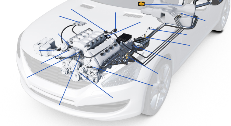
Today's electronically controlled engines deliver excellent performance, good fuel economy and minimal pollution. Without powerful onboard vehicle computer(s) and software that manage all aspects of fuel delivery, ignition timing and emissions control, this level of precise system adjustments and monitoring would be impossible. The vehicle’s computer (PCM), sensors and diagnostic programming continually monitor various engine control system parameters determining whether the vehicle is operating as originally designed.
OBD II diagnostic software monitors performance whenever the vehicle is operating and signals the motorist if conditions exist that could allow tailpipe emissions to exceed 1.5 times the level the vehicle was EPA certified for or if there is a possibility of engine damage or fire.
The PCM's job is to manage the powertrain. This includes the engine's ignition system, fuel injection system and emission controls. The PCM receives inputs from a wide variety of sensors and switches. In turn the PCM controls, directly or indirectly, components to achieve proper ignition timing, fuel delivery and proper treatment of pollutants. Let’s look at some of the vehicle systems the PCM and the OBD II system control.
Powertrain Control Module (PCM)
The PCM's job is to manage the powertrain. This includes the engine's ignition system, fuel injection system and emission controls. The PCM receives inputs from a wide variety of sensors and switches. In turn the PCM controls directly or indirectly relays, solenoid and other components to achieve proper ignition timing, fuel delivery and proper treatment of pollutants. The vehicle’s PCM, sensors and diagnostic programming continually monitor various engine control system parameters determining whether the vehicle is operating as originally designed.
The control of idle speed is a function of the PCM on all OBD II equipped vehicles. The PCM can control the amount of air that bypasses the throttle when the throttle is fully closed, thereby controlling the engine's idle RPM. Electronically controlling the air enables just the right amount of air needed to maintain the desired idle RPM. This also allows the PCM to dynamically respond to changes in engine load when the A/C compressor is engaged, the alternator is charging above a certain voltage, and/or the automatic transmission is in gear.
OBD II diagnostic software monitors performance whenever the vehicle is operating and signals the motorist if conditions exist that could allow tailpipe emissions to exceed 1.5 times the level the vehicle was EPA certified for or if there is a possibility of engine damage or fire.
Another important function of the PCM is to communicate system operating conditions and diagnostic information to the motorist and if needed, repair personnel. On OBD II equipped vehicles this accomplished two ways. The first is through the Check Engine Light, sometimes referred to as the malfunction indicator light (MIL), that is located on the dashboard display panel. The second method of communicating with the PCM is by using an OBD II diagnostic scan tool.
Let’s take a look at the sensors and components the PCM interacts with to control the various systems on OBD II compliant vehicles.
Check Engine Light
The check engine light illuminates to alert the motorist that there is a malfunction of the powertrain or engine management system. It is found on the instrument panel of most automobiles. On vehicles equipped with OBD-II, the light indicates two levels of fault detection. When the light is illuminated steady this indicates a minor fault such as a loose gas cap or failing oxygen sensor. If the light is flashing a severe fault is indicate that may damage the catalytic converter if not addressed. When the MIL is lit, the engine control unit stores a fault code related to the malfunction, which can be retrieved with a scan tool and used for further diagnosis.
The check engine light will illuminate during engine operation if a system fault is detected by the PCM that could possibly cause an increase in emissions. Whenever the Check Engine light comes on a diagnostic trouble code (DTC) is also recorded in the PCM’s memory that corresponds to the fault. Some problems can generate more than one DTC code, and some vehicles may suffer from multiple problems that also set multiple codes. The check engine light may turn on and go off, remain on continuously or flash. Some types of intermittent problems will make the lamp come on only while the fault is occurring. When the problem goes away, the lamp goes off. Other types of problems will turn the light on, and it will remain on until the fault is diagnosed and repaired.
The check engine light is very useful for spotting problems quickly, but it does not provide specific information about vehicle operation. More detailed diagnostics can be performed with an OBD II diagnostic scan tool. The scan tool is attached to the diagnostic link connector (DLC) connector located under the dashboard on the driver side of the vehicle. The scan tool will decipher the error code stored in the vehicle's PCM along with many other diagnostic signals to help repair personnel pinpoint the source of the malfunction.
Diagnostic Link Connector (DLC)
The DLC on OBD II equipped vehicles is a standardized 16 pin diagnostic connector used to interface a scan tool with the PCM allowing access to on-board diagnostics and live data streams. Most manufacturers have made the OBD-II Data Link Connector the only one in the vehicle through which all systems are diagnosed and programmed.
Front Oxygen Sensor
The oxygen sensor provides real time information about the air/fuel mixture. The PCM uses this to constantly re-adjust and fine tune the air/fuel ratio. This reduces emissions and optimizes fuel efficiency and performance. A faulty oxygen sensor will typically make an engine run rich, use more fuel and pollute.
Rear Oxygen Sensor
The downstream oxygen sensor functions the same as the upstream oxygen sensor in the exhaust manifold. The sensor produces a voltage that changes when the amount of unburned oxygen in the exhaust changes. The high or low voltage signal tells the PCM the fuel mixture is rich or lean.
The downstream oxygen sensor is primarily used during monitoring of catalytic converter efficiency. The PCM monitors converter efficiency by comparing the upstream and downstream oxygen sensor signals. If the converter is doing its job and is reducing the pollutants in the exhaust, the downstream oxygen sensor should show little activity. If the signal from the downstream oxygen sensor starts to mirror that from the upstream oxygen sensor it means converter efficiency has dropped off and the converter isn’t cleaning up the pollutants in the exhaust. When the converter efficiency appears to have declined to the point where the vehicle may be exceeding the pollution limit the PCM will turn on the Check Engine Lamp and set a diagnostic trouble code.
Mass Air Flow Sensor (MAF)
The mass air flow sensor (MAF) is used to measure the flow rate of air entering a fuel injected engine. The PCM uses air mass information to calculate and deliver the correct amount of fuel to the cylinders under all engine operating conditions. The sensor is located in the air induction piping before the throttle body and produces an electrical signal to the PCM that varies proportional with the air volume flowing into the engine. The MAF sensor is the primary input to the PCM with regards to air flow information, and the oxygen sensor provides closed-loop feedback in order to make real time corrections to the air/fuel mixture being combusted.
Any air entering the air induction system after the mass air flow sensor will not be accounted for by the PCM and an improper air/fuel mixture may occur. This will result in poor performance, less fuel efficient engine operation and the possibility of producing excessive emissions.
The screen protecting the mass air flow sensor can accumulate debris creating incorrect readings. When the PCM suspects there is an issue with the mass air flow sensor it will set a DTC code and illuminate the Check Engine light.
Manifold Absolute Pressure Sensor (MAP)
On some fuel injection systems a manifold absolute pressure sensor (MAP) is used to calculate air volume entering the engine. The MAP sensor outputs an electrical signal to the PCM indicating instantaneous manifold pressure information. This data along with engine speed and air temperature is used to calculate air density and determine the engine's air mass flow rate, which in turn determines the required fuel metering for optimum combustion and. Most fuel injection systems will usually have either a MAP sensor or a mass air flow, not both.
Coolant Temperature Sensor CTS)
The coolant sensor monitors engine temperature. The PCM uses this information to regulate a wide variety of ignition, fuel and emission control functions. For instance, when the engine is cold the air/fuel mixture needs to be richer to improve drivability. The PCM also uses the signal from the coolant sensor to determine when the vehicle is ready to run certain diagnostic monitors. IF the PCM suspects that there is any issue with the CTS sensor it will set a DTC code and illuminate the Check Engine light.
Air Temperature Sensor (ATS)
The air temperature sensor is often referred to as the intake air temperature sensor or the manifold air temperature sensor and is used to measure the temperature of the air being drawn into the engine. The PCM uses the signal from this sensor to modify the base air/fuel mixture being combusted in the cylinders. This helps with reducing emissions and improving engine performance. If the PCM suspects that there is any issue with the ATS sensor it will set a DTC code and illuminate the Check Engine light.
Throttle Position Sensor (TPS)
The throttle position sensor (TPS) is usually connected to the throttle plate shaft in the throttle body. The TPS reads the angle of the throttle valve and transmits an electrical signal to the PCM. The PCM uses this real time signal to help calculate or modify fuel injector pulse width, controlling air/fuel mixture. If the PCM suspects that there is any issue with the TPS sensor it will set a DTC code and illuminate the Check Engine light.
Crankshaft Position Sensor
The crankshaft position sensor does two things, it monitors engine rpm and helps the computer determine relative position of the crankshaft so the PCM can control spark timing and fuel delivery in the proper sequence. On some engines, an additional camshaft position sensor is used to provide additional input to the PCM about valve timing.
Vehicle Speed Sensor (VSS)
The vehicle speed sensor (VSS) keeps the PCM informed about how fast the vehicle is traveling. This is needed to control functions such as torque converter lockup. The PCM also uses the VSS signal to determine when the vehicle is ready to run many of the non-continuous diagnostic monitors. If the PCM suspects that there is any issue with the VSS sensor it will set a DTC code and illuminate the Check Engine light.
Fuel Tank Pressure Sensor
The fuel tank pressure sensor is part of the fuel pump sending unit assembly and is mounted on top of the fuel tank or inside the tank. The fuel tank pressure sensor measures the positive and negative pressure in the fuel tank. The sensor reads pressure in the fuel tank primarily during EVAP system monitoring. The PCM uses the pressure reading to detect evaporative leaks. When readings from the sensor indicate a leak, or if the sensor itself fails, the PCM sets a DTC code and illuminates the Check Engine light.
Canister Purge Solenoid
The canister purge valve or purge solenoid is an electrically operated valve that allows engine vacuum to draw gasoline vapors from the EVAP canister. The PCM energizes the purge solenoid during normal driving conditions and also operates the valve during EVAP system monitoring. The PCM can detect any electrical issues with the solenoid whenever the engine is running through a process known as continuous component monitoring. The PCM can assess the valve's ability to hold and release vacuum during EVAP system monitoring. In either case if the PCM detects an issue, the PCM sets a DTC code and illuminates the Check Engine light.
EGR Solenoid
On most OBD II equipped vehicles, the EGR valve is controlled by the PCM. If the engine has a vacuum-operated EGR valve, the PCM controls a solenoid in the vacuum line to open and close the valve. The PCM may cycle the solenoid on and off to vary the EGR flow rate. Increasing the activation time of the solenoid holds the valve open longer and increases the flow rate.
Idle Speed Control Motor
Idle speed on fuel injected engines is controlled by the PCM through an idle air bypass circuit on the throttle body. The idle speed control motor is a small electric motor or solenoid that is used to open and close the bypass orifice. The larger the opening, the greater the volume of air that can bypass the throttle plates and the faster the idle speed. The PCM controls the idle whenever the engine is operating compensating for engine loads and engine temperature variations. If the PCM cannot achieve a desired idle rpm or there is an electrical issue with the idle speed control motor, the PCM sets a DTC code and illuminates the Check Engine light.
Leak Detection Pump
Some vehicle manufactures use a leak detection pump as a pressure source for conducting positive pressure testing of the EVAP system during EVAP system monitoring. The LDP is a diaphragm pump with solenoids and check valves that pump air into the fuel tank and charcoal canister. The PCM controls the operation of the LDP during EVAP system monitoring. Once the EVAP system is pressurized the PCM can measure the system's pressure decay.
The PCM can detect any electrical issues with the leak detection pump whenever the engine is running through a process known as continuous component monitoring. The PCM can assess the LDPs ability to create and hold pressure during EVAP system monitoring. In either case if the PCM detects an issue, the PCM sets a DTC code and illuminates the Check Engine light.